Aircraft landing gear supports the entire weight of an aircraft during ground operations. Every takeoff, landing, and taxiing maneuver depends on this system functioning correctly.
Landing gear absorbs tremendous forces during touchdown. A commercial airliner landing at 150 mph generates impact loads exceeding 500,000 pounds. The system must dissipate this energy safely while protecting passengers, crew, and aircraft structure.
This guide explains how aircraft landing gear works, from shock absorption mechanisms to braking systems and safety redundancies. We’ll cover the components, types, and engineering principles that make safe aircraft operations possible.
What Is Aircraft Landing Gear?

Aircraft landing gear is the structural system that supports an aircraft on the ground. The system consists of wheels, shock absorbers, brakes, steering mechanisms, and structural attachments to the airframe.
Primary functions of landing gear:
- Support aircraft weight during ground operations
- Absorb landing impact forces and dissipate energy
- Provide braking capability for landing and taxiing
- Enable ground steering and maneuvering
- Withstand loads during takeoff acceleration
- Retract into aircraft structure during flight (on retractable gear)
Landing gear represents 3-5% of an aircraft’s total weight. A Boeing 777 landing gear system weighs approximately 15,000 pounds. This weight proves necessary to handle the structural loads and dynamic forces aircraft experience during ground operations.
Main Types of Aircraft Landing Gear
Aircraft use different landing gear configurations based on size, performance requirements, and operational environment.
Tricycle Landing Gear

Tricycle configuration features one nose gear and two main landing gear assemblies. This design dominates modern aviation.
Advantages:
- Stable ground handling characteristics
- Level cabin floor during ground operations
- Reduced risk of nose-over during braking
- Improved visibility for pilots during taxiing
- Protection against tail strikes during takeoff rotation
Used on: All commercial airliners, most business jets, modern military aircraft, majority of general aviation aircraft
Tailwheel (Conventional) Landing Gear

Conventional gear positions two main wheels forward with a small tail wheel aft. This configuration was standard on early aircraft.
Characteristics:
- Propeller clearance advantages on unpaved surfaces
- Lighter weight than tricycle gear
- Less stable during ground operations (requires more pilot skill)
- Reduced forward visibility during taxiing
Used on: Vintage aircraft, aerobatic aircraft, bush planes, some agricultural aircraft
Fixed Landing Gear
Fixed gear remains extended during flight. Wheels and struts stay exposed to airflow.
Advantages:
- Simpler system with fewer components
- Lower maintenance requirements
- Reduced weight (no retraction mechanism)
- Lower manufacturing cost
- Eliminates gear extension failure risk
Disadvantages:
- Higher drag reduces speed and fuel efficiency
- Limited to lower performance aircraft
Used on: Light general aviation aircraft, trainers, bush planes, ultralight aircraft
Retractable Landing Gear
Retractable gear retracts into wing, fuselage, or nacelle during flight. This eliminates drag and improves performance.
Advantages:
- Reduced drag increases speed by 15-25%
- Improved fuel efficiency on longer flights
- Higher maximum speeds achievable
Complexity added:
- Hydraulic or electric retraction systems
- Uplocks and downlocks
- Position indicators and warning systems
- Emergency extension mechanisms
Used on: All commercial jets, business jets, high-performance general aviation, military aircraft
Main Components of an Aircraft Landing Gear System
Landing gear systems integrate multiple components working together to support aircraft operations.
Wheels and Tires

Aircraft tires handle extreme loads and speeds. A Boeing 737 main tire supports approximately 30,000 pounds during landing.
Key specifications:
- Inflation pressure: 200-250 psi (significantly higher than automotive tires at 30-35 psi)
- Materials: Reinforced rubber compounds with multiple plies
- Speed rating: Up to 225 mph for large jets
- Inflation medium: Nitrogen (prevents combustion risk, maintains pressure stability)
Tires feature tread grooves that channel water away during wet runway operations. Commercial aircraft tires last 200-300 landings before requiring replacement.
Oleo-Pneumatic Shock Absorbers

Oleo struts absorb landing impact through hydraulic fluid and compressed gas working together. This system represents the primary shock absorption mechanism on modern aircraft.
How oleo struts work:
Upper chamber contains compressed nitrogen gas. Lower chamber contains hydraulic fluid. During landing compression, hydraulic fluid flows through orifices into the gas chamber. This compresses the gas while creating hydraulic damping. Gas compression stores energy. Hydraulic flow controls compression rate.
As gear extends after compression, gas pressure pushes hydraulic fluid back through orifices. This controlled extension prevents bouncing and provides smooth operation.
Performance characteristics:
- Absorbs vertical loads up to 10 feet per second sink rate
- Dissipates kinetic energy as heat in hydraulic fluid
- Prevents aircraft bounce after touchdown
- Maintains consistent damping across temperature ranges
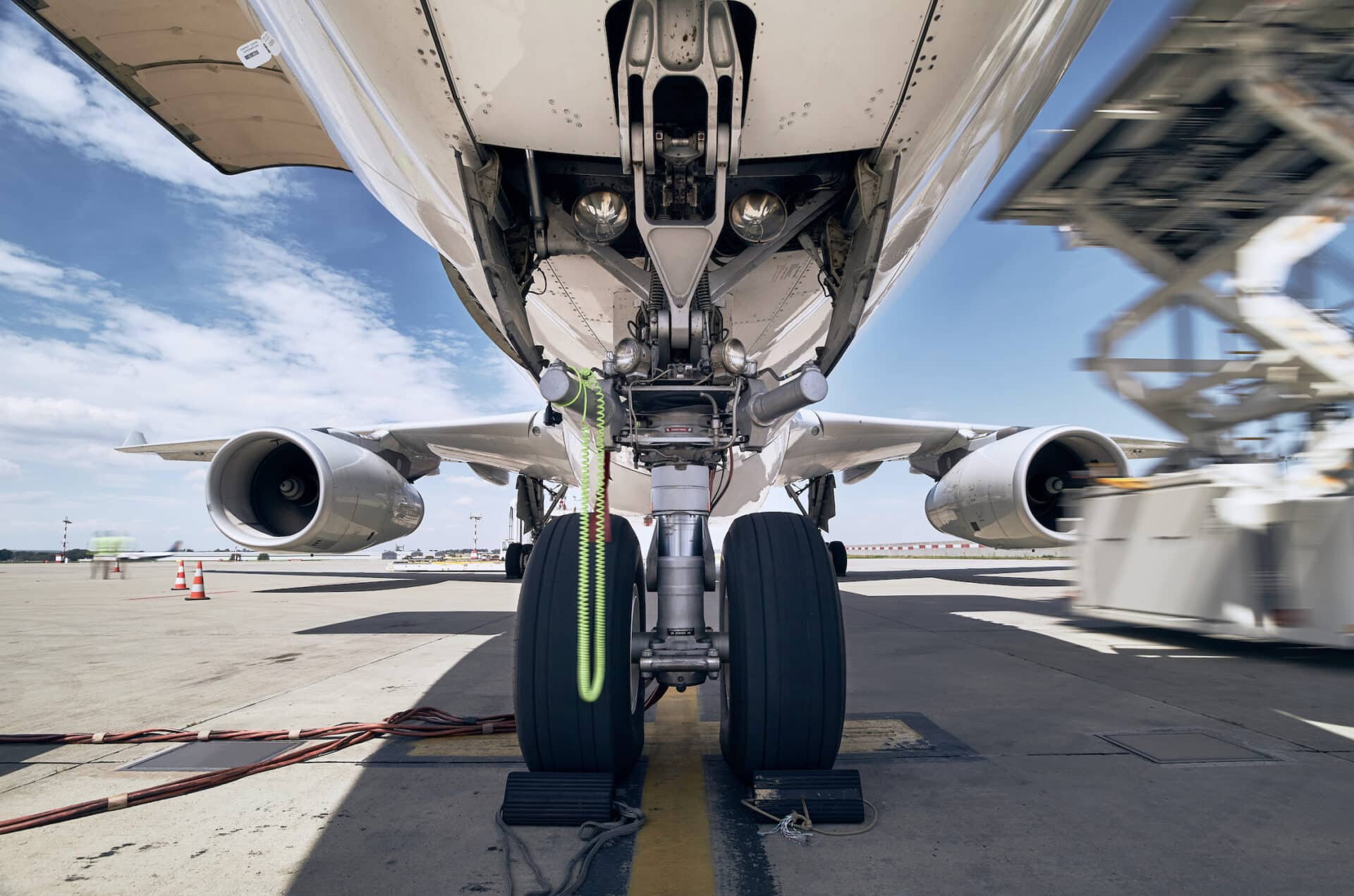
Struts and Bogies

Structural struts connect landing gear to aircraft airframe. These components transfer all ground loads into the aircraft structure.
Main strut: Vertical structural member containing shock absorber mechanism. Attaches to aircraft via trunnion fitting (pivot point for retraction).
Bogie: Beam connecting multiple wheel assemblies on heavy aircraft. Boeing 777 main gear features a six-wheel bogie. Airbus A380 main gear uses five bogies with 20 total wheels. Bogies distribute weight across multiple tires.
Materials:
- High-strength steel alloys for structural components
- Titanium alloys for weight-critical applications
- Aluminum alloys for secondary structures
Braking System

Aircraft brakes convert kinetic energy to thermal energy, bringing aircraft to a stop. Landing speeds reaching 150-180 mph require substantial braking capability.
Multi-disc brakes: Modern aircraft use carbon-carbon disc brakes. Multiple discs stack together, alternating between rotating and stationary discs. Hydraulic pressure clamps discs together, creating friction.
Carbon brake advantages:
- Lighter weight than steel brakes (40% reduction)
- Superior heat dissipation capabilities
- Longer service life (2,000+ landings vs 500 for steel)
- Consistent performance at high temperatures
- Operating temperatures reach 1,500-2,000°F during maximum braking
Hydraulic brake system: Multiple hydraulic systems provide redundancy. Boeing 787 features independent hydraulic circuits for each brake. If one system fails, alternative systems maintain braking capability.
Steering System

Nose wheel steering enables precise ground maneuvering. Pilots control steering through rudder pedals (low speed) or dedicated tiller wheel (high precision turns).
Steering mechanisms:
- Hydraulic actuators: Convert pilot input to wheel angle
- Steering angle range: Typically 70-80 degrees maximum deflection
- Rudder pedal steering: Limited to approximately 7-10 degrees for taxiing
- Tiller steering: Provides full deflection range for tight turns
Main landing gear on some widebody aircraft features limited steering capability to reduce tire scrubbing during turns.
Retraction and Extension Mechanism

Hydraulic actuators retract and extend landing gear. The system includes mechanical locks, position sensors, and emergency backup systems.
Retraction sequence (typical):
- Weight-on-wheels sensors confirm aircraft is airborne
- Gear selector moved to UP position
- Downlocks release
- Hydraulic actuators retract gear
- Gear doors open (if applicable)
- Gear retracts into wheel well
- Uplocks engage to secure gear
- Gear doors close
Extension follows reverse sequence with downlocks engaging to secure gear in extended position.
How Aircraft Landing Gear Absorbs Landing Impact
Landing generates massive vertical forces. A 150,000-pound aircraft touching down at 600 feet per minute vertical speed creates impact forces exceeding 300,000 pounds.
Energy dissipation process:
Initial contact: Tires compress first, absorbing initial impact. Tire deflection provides first cushioning stage.
Oleo compression: Landing gear strut compresses as hydraulic fluid flows through metering orifices. Orifice size controls compression rate. Too fast creates hard landing sensation. Too slow allows excessive compression.
Gas compression: Nitrogen gas compresses as hydraulic fluid enters upper chamber. Gas acts as spring, storing energy for extension. Compression ratio reaches 3:1 or 4:1 during hard landing.
Hydraulic damping: Fluid flowing through orifices creates resistance. This converts kinetic energy to heat. Hydraulic fluid temperature rises 50-100°F during hard landing.
Extension damping: As gear extends after compression, orifices meter fluid flow back to lower chamber. This prevents aircraft bounce. Damping ensures single controlled extension rather than multiple bounces.
Entire process occurs in less than one second, protecting aircraft structure and passengers from damaging impact forces.
Nose Gear vs Main Landing Gear: Key Differences
Nose and main landing gear serve different functions and handle different loads.
| Feature | Nose Gear | Main Landing Gear |
|---|---|---|
| Weight Distribution | 10-15% of aircraft weight | 85-90% of aircraft weight |
| Primary Function | Steering and directional control | Weight support and braking |
| Brakes | No brakes (steering only) | Full braking system |
| Wheel Count | 2 wheels (single axle) | 4-20 wheels (multiple bogies possible) |
| Structural Loads | Lower loads, lighter construction | Highest loads, reinforced structure |
| Retraction Direction | Forward or aft into fuselage | Inward into wing or fuselage |
| Shock Absorption | Lighter duty oleo strut | Heavy duty oleo strut with greater travel |
Main landing gear attachment points connect to wing box or center fuselage structure. These represent the strongest structural areas on aircraft. Nose gear attaches to forward fuselage structure with lighter reinforcement requirements.
How Landing Gear Retraction and Extension Works
Retractable landing gear systems use hydraulic power to retract gear into aircraft structure during flight. This eliminates drag and improves performance.
Hydraulic System Operation
Hydraulic actuators provide the force to move landing gear. Aircraft hydraulic systems operate at 3,000 psi pressure. This high pressure delivers substantial force through compact actuators.
Retraction actuator: Double-acting hydraulic cylinder connects to landing gear via linkages. Hydraulic pressure applied to one side extends actuator. Pressure applied to opposite side retracts actuator.
Multiple actuators coordinate movement: Main landing gear might use primary retraction actuator plus secondary actuators for gear doors. Mechanical linkages synchronize all movements.
Uplocks and Downlocks
Mechanical locks secure landing gear in both extended and retracted positions. These prevent uncommanded movement.
Uplock mechanism: Spring-loaded hook engages with striker plate when gear reaches fully retracted position. Uplock holds gear securely during flight. Hydraulic pressure releases uplock during extension sequence.
Downlock mechanism: Over-center linkage locks gear in extended position. Geometry creates mechanical advantage preventing collapse. Weight and air loads force lock deeper into engagement. Requires hydraulic pressure to unlock for retraction.
Safety features:
- Downlocks engage automatically when gear extends
- Ground safety pins physically lock gear down during maintenance
- Weight-on-wheels sensors prevent retraction on ground
- Backup mechanical systems provide redundancy
Gear Sequencing
Landing gear retracts and extends in programmed sequence. This prevents interference between components.
Typical retraction sequence:
- Downlocks release
- Gear doors open
- Main gear retracts
- Nose gear retracts (slight delay to clear main gear)
- All gear secured in uplocks
- Gear doors close
Total retraction time: 10-20 seconds depending on aircraft type.
Emergency Extension Systems
Multiple backup systems ensure landing gear extends if normal hydraulics fail.
Alternate extension methods:
- Gravity extension: Uplocks release, gear falls under own weight and air loads. Most reliable backup method.
- Pneumatic system: Compressed nitrogen cylinders power emergency actuators. Independent of main hydraulic system.
- Electric motor: Battery-powered motor drives gear extension on some aircraft. Provides slow but reliable extension.
- Manual extension: Hand crank mechanically drives gear down. Labor-intensive but mechanically simple. Used on smaller aircraft.
Emergency extension procedures require crew coordination and take longer than normal extension (30-60 seconds typical).
Aircraft Braking Systems Explained
Brakes convert aircraft kinetic energy to heat, enabling controlled deceleration. A Boeing 777 landing at maximum weight must dissipate energy equivalent to 150 million foot-pounds during landing rollout.
Wheel Brake Components
Brake assembly consists of:
- Stators: Stationary discs attached to axle. Remain fixed.
- Rotors: Rotating discs attached to wheel. Rotate with wheel.
- Pressure plate: Applies clamping force to disc stack.
- Hydraulic piston: Converts hydraulic pressure to mechanical force.
- Brake housing: Contains entire assembly and connects to landing gear.
Disc count varies by aircraft size. Boeing 737 uses 5-6 discs per brake. Boeing 777 uses 7-8 discs. Airbus A380 uses up to 10 discs per brake position.
Carbon Brakes
Carbon-carbon composite brakes replaced steel on most commercial aircraft. Carbon material withstands extreme temperatures while reducing weight.
Performance advantages:
- Operating temperature range: -60°F to 2,000°F
- Weight savings: 600-1,200 pounds per aircraft
- Service life: 2,000-3,000 landings before overhaul
- Consistent friction coefficient across temperature range
- Reduced wheel and tire wear (less heat transfer)
Carbon brake manufacturing involves complex heat treatment process creating carbon-carbon matrix structure. Material costs more than steel but total lifecycle costs prove lower.
Anti-Skid Systems
Anti-skid prevents wheel lockup during braking. Locked wheels lose directional control and cause tire damage through flat spotting.
System operation:
Wheel speed sensors monitor each wheel independently. Computer compares wheel speeds. If one wheel decelerates faster than others, anti-skid reduces brake pressure to that wheel. This prevents lockup while maintaining maximum braking force.
Benefits:
- Shortest stopping distances on all surfaces
- Maintained directional control during braking
- Reduced tire wear
- Effective on contaminated runways (water, snow, ice)
Anti-skid systems cycle brake pressure 10-15 times per second, providing precise control.
Autobrake Function
Autobrake automatically applies brakes after landing or during rejected takeoff. Pilots select desired deceleration rate before landing.
Available settings (typical):
- RTO (Rejected Takeoff): Maximum braking if takeoff aborted
- MIN: Gentle deceleration for long runways
- MED: Moderate braking for normal operations
- MAX: Maximum braking for short runways
Autobrake engages when wheel spin-up occurs (touchdown detection) and thrust levers reach idle. System applies smooth, consistent braking pressure. Pilots can override by applying manual brakes at any time.
Steering and Ground Maneuvering
Precise ground maneuvering requires effective steering systems. Aircraft must navigate taxiways, make tight turns at gates, and maintain centerline during takeoff and landing.
Nose Wheel Steering
Hydraulic actuators rotate the nose wheel based on pilot input. Two control methods exist:
Rudder pedal steering: Conventional rudder pedals provide limited steering authority (typically 7-10 degrees maximum). Sufficient for runway operations and gentle turns during taxiing. Allows pilots to maintain directional control during takeoff and landing rollout.
Tiller control: Hand-operated tiller wheel provides full steering range (70-80 degrees). Located on side console near pilot’s left hand. Enables sharp turns and precise positioning during gate operations. Required for tight radius turns on taxiways.
Steering Actuator Design
Hydraulic steering actuator connects to nose gear strut. Actuator extends and retracts based on pilot input, rotating the strut and wheels. Mechanical feedback provides steering feel to pilot. System includes centering mechanism that returns wheels to neutral when control input released.
Taxi Operations
Large aircraft require substantial turning radius even with maximum steering. Boeing 777 turning radius exceeds 80 feet with full tiller input. Modern widebody aircraft feature main landing gear steering on some models to reduce turning radius and minimize tire scrubbing.
Pilots coordinate power, brakes, and steering to maneuver on ground. Differential thrust (asymmetric engine power) assists turns on multi-engine aircraft. Differential braking provides backup steering if nose wheel steering fails.
Safety Systems in Aircraft Landing Gear

Multiple redundant safety systems protect against landing gear failures.
Weight-on-Wheels Sensors
Switches mounted on landing gear struts detect aircraft weight. These sensors serve critical safety functions:
- Prevent gear retraction on ground (mechanical safety interlock)
- Enable ground-only systems (thrust reversers, ground spoilers)
- Disable air-only systems (autopilot, autothrottle)
- Trigger autobrake engagement after landing
- Control flight control modes (ground vs flight configurations)
Redundant sensors prevent single-point failures. Typical installation uses two independent sensors per gear.
Brake Temperature Monitoring
Brake temperature sensors monitor heat buildup in brake assemblies. After landing, brakes can reach 800-1,500°F under normal conditions. Rejected takeoff at maximum weight generates temperatures exceeding 2,000°F.
Safety implications:
- High temperature brake fires possible if wheels/tires overheat
- Fusible plugs in wheels melt at predetermined temperature, deflating tires before explosion risk
- Ground crews check brake temperatures before approach
- Minimum cooling time required before next takeoff
Some aircraft display brake temperatures in cockpit. Others require ground crew with handheld pyrometers.
Gear Position Indicators
Pilots must verify landing gear position before landing. Multiple indication systems provide redundancy:
Primary indicators: Electronic displays show gear position (up, in transit, down and locked). Green lights indicate all gear down and locked. Red indication shows unsafe configuration.
Backup indicators: Mechanical linkages drive physical position indicators visible in cockpit. Function independently of electrical system.
Visual inspection: Some aircraft feature viewing ports allowing crew to visually verify main gear extension.
Redundancy and Fail-Safe Design
Landing gear systems incorporate multiple levels of redundancy:
- Multiple hydraulic systems: Independent hydraulic sources power gear extension
- Emergency extension: Gravity/pneumatic/electric backup systems
- Structural redundancy: Load paths designed to continue functioning with component failures
- Overstress protection: Fuse pins shear during overload to protect primary structure
Commercial aircraft must demonstrate continued safe flight and landing with complete hydraulic system failure. Emergency extension systems meet this requirement.
Common Landing Gear Failures (And Why They’re Rare)

Landing gear failures occur infrequently due to redundant design and rigorous maintenance programs. When failures do occur, aircraft design enables safe outcomes.
Tire Failures
Causes: Debris damage, excessive wear, overheating, manufacturing defects. Tire failures represent the most common landing gear issue.
Design protection: Multiple tires per landing gear. Aircraft certified to land safely with failed tires. Remaining tires handle additional load. Wheel rims designed to support aircraft temporarily if tire completely deflates.
Hydraulic Leaks
Causes: Seal failures, actuator damage, hydraulic line rupture. Leaks reduce system pressure, potentially preventing gear retraction or extension.
Design protection: Multiple independent hydraulic systems. Emergency extension systems operate without hydraulics. Pilots detect leaks through pressure gauges and fluid quantity indicators.
Gear Indication Issues
Causes: Sensor failures, wiring problems, switch malfunctions. Crew receives unsafe gear indication despite gear actually extended and locked.
Resolution: Backup indication systems provide redundant information. Visual inspection from other aircraft or ground confirms actual gear position. Emergency procedures guide crew through verification process.
Structural Failures
Causes: Hard landings, manufacturing defects, corrosion, maintenance errors. Structural failures are extremely rare due to inspection programs and fail-safe design.
Design protection: Multiple load paths prevent complete failure. Damage tolerance design allows aircraft to land with damaged components. Regular inspections detect cracks before propagation to critical size.
Why failures are rare: Inspection intervals measured in flight cycles and calendar time. Non-destructive testing detects internal defects. Replacement criteria conservative with significant safety margins. Component testing proves reliability before certification. Statistical analysis identifies trends before fleet-wide issues develop.
Landing Gear on Different Aircraft Types
Landing gear design scales with aircraft size and weight while maintaining similar principles.
Narrowbody Aircraft
Boeing 737 and Airbus A320 family represent typical narrowbody configurations. Two main landing gear assemblies with two wheels each. Single nose gear with two wheels. Total six wheels.
Main gear retracts inward into fuselage wells. Simple linkage mechanisms. Hydraulic retraction with gravity extension backup. Carbon brakes standard on modern variants.
Widebody Aircraft
Boeing 777 and 787, Airbus A350 and A380 feature more complex gear systems. Multiple wheels distribute higher weights across runways.
Boeing 777 uses six-wheel bogies on main gear (12 total main wheels). Airbus A380 employs five landing gear assemblies with 20 main wheels plus two nose wheels (22 total wheels). This weight distribution prevents runway damage and enables operation at airports with lower load-bearing pavements.
Cargo Aircraft
Freighter variants often use reinforced landing gear for increased maximum weights. Additional structural reinforcement handles higher landing loads. Strengthened shock absorbers manage heavier touchdown impacts. Higher capacity brakes dissipate greater kinetic energy.
Some cargo aircraft feature kneeling capability. Hydraulic actuators compress nose gear, lowering cargo door for easier loading.
Business Jets
Gulfstream G650, Bombardier Global series, and similar jets use simpler four or six-wheel configurations. Weight and size allow lighter duty components. Retraction mechanisms similar to commercial aircraft but smaller scale. Performance requirements demand retractable gear.
Why Aircraft Landing Gear Is So Heavy
Landing gear represents significant portion of aircraft empty weight despite appearing simple. Multiple factors drive weight requirements.
Structural Loads
Certification standards require landing gear to withstand multiple load cases:
- Vertical landing loads: 2.0-2.5 times aircraft maximum landing weight
- Braking loads: Horizontal forces during maximum braking
- Side loads: Crosswind landings generate lateral forces
- Turning loads: Sharp turns during ground operations
- Spring-back loads: Gear extension generates dynamic loads
Each load case requires structural sizing. Worst-case loading determines component dimensions. Multiple load cases combine requiring robust design.
Safety Margins
Certification requires ultimate load factors of 1.5 times limit loads. Limit load represents maximum expected operational load. Structure must support 1.5 times this without failure. Additional margins account for material variability, manufacturing tolerances, and degradation over service life.
Certification Requirements
Regulators demand extensive testing proving landing gear strength and reliability. Drop tests simulate hard landings. Fatigue testing cycles components through millions of loading cycles. Environmental testing verifies function across temperature extremes. Wear testing validates maintenance intervals.
Meeting certification standards while minimizing weight represents significant engineering challenge. Advanced materials like titanium alloys and carbon fiber composites help reduce weight while maintaining strength. Computer modeling optimizes structural efficiency. Despite these advances, landing gear remains heavy due to fundamental load requirements.
Frequently Asked Questions
How does aircraft landing gear work?
Landing gear uses oleo-pneumatic struts combining hydraulic fluid and nitrogen gas to absorb impact. Hydraulic brakes slow aircraft after touchdown. Hydraulic actuators retract gear during flight, reducing drag.
Why do planes retract landing gear?
Retracting gear eliminates aerodynamic drag, increasing speed 15-25% and significantly improving fuel efficiency. Extended gear creates turbulent airflow producing substantial drag that retraction systems eliminate.
What absorbs shock when a plane lands?
Oleo-pneumatic struts absorb landing shock. Hydraulic fluid flows through orifices into gas chamber, compressing nitrogen while creating damping. This dissipates kinetic energy as heat.
What happens if landing gear fails?
Emergency extension systems (gravity, pneumatic, electric) provide backup. If gear truly cannot extend, pilots perform gear-up landing on runway. Aircraft belly designed to slide safely.
Why are aircraft tires filled with nitrogen?
Nitrogen prevents combustion risk if tires overheat. It’s inert and maintains stable pressure across temperature changes, unlike air which contains moisture causing variability.
How fast do aircraft land?
Commercial jets typically land at 130-160 mph depending on weight and type. Boeing 737 lands around 130-145 mph. Boeing 777 touches down around 145-160 mph.
Can planes land without landing gear?
Yes, aircraft can perform gear-up landings in emergencies. Pilots touch down on aircraft belly. Fuselage designed to protect cabin during gear-up landing. Damage extensive but injuries rare.
How many times can aircraft landing gear be used?
Commercial aircraft landing gear lasts 20,000-50,000 flight cycles before major overhaul. Tires replaced every 200-300 landings. Carbon brakes last 1,500-3,000 landings.
Conclusion: Engineering Excellence Enables Safe Flight Operations
Aircraft landing gear represents sophisticated engineering system balancing multiple competing requirements. Weight minimization conflicts with structural strength needs. Complexity of retractable systems adds failure modes requiring redundant safety features. Cost pressures compete against reliability requirements.
Modern landing gear systems successfully navigate these challenges through careful design, extensive testing, and rigorous maintenance programs. Oleo-pneumatic shock absorbers reliably dissipate landing energy. Carbon brakes provide consistent performance across wide temperature ranges. Multiple redundant systems ensure gear extension even during failures.
Millions of successful takeoffs and landings prove landing gear system effectiveness. Failures occur rarely and usually resolve without consequence. Continued engineering refinement further improves reliability while reducing weight and cost.
Understanding how landing gear works illuminates the engineering excellence enabling modern aviation safety record. Every component serves specific purpose. Every system includes backup. Every design decision balances safety against weight and complexity.
Aircraft landing gear exemplifies aerospace engineering principles: sophisticated solutions to complex problems, rigorous attention to safety, and elegant integration of mechanical, hydraulic, and electronic systems working together flawlessly.